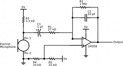
If you are working on a project that responds to sounds, your circuit will require some type of microphone to transduce the sound into a modulated voltage and, most likely, some type of amplification of this modulated voltage. I like to use electret microphones to transduce sound because they require relatively simple circuits. For example, the circuit below passes the output of an electret microphone (hooked up according to its datasheet) through a band-pass amplifier based on an LM358 operational amplifier. This circuit is suitable for a 5-V system. The op-amp circuit has both a high-pass portion (R1 and C1) and a low-pass portion (R2 and C2). Thus, the circuit attenuates frequencies below f = 1/(2πR1C1) = 5.9 Hz and frequencies above f = 1/(2πR2C2) = 15915 Hz. The op-amp acts like an inverting amplifier with a gain of -R2/R1=37. The voltage divider (R4 and R5) is used to give the output about a 1.6 V DC offset. This allows both the positive and negative portions of the input to be amplified and present in the output. After building this circuit, I discovered a very similar circuit is implemented by SparkFun’s electret microphone breakout board but different resistor and capacitor values are used yielding a different gain and different band-pass characteristics, a different op amp is used, and a capacitor is placed in parallel with R4 presumably to stabilize the voltage to the non-inverting input of the op-amp. This additional capacitor may be a good idea, but I actually think my circuit is superior in that the voltage divider introduces a smaller DC offset that more closely matches the midpoint of the op-amp’s dynamic range when powered by 5 volts. Just my opinion.
Previous Post: IR Photodiode Circuit Schematic
Next Post: Making a PDF of a Microsoft Word Document

Permalink //
Just the circuit I was looking for, especially since it uses the 358 that’s been a real workhorse op-amp for me.