Capacitors are electronic devices that can store electric charge. The amount of charge (Q) a capacitor can hold per volt (V) is called the capacitor’s capacitance (C) and has SI units of farads.
C = Q/VCapacitors are used for myriad reasons. You will find capacitors in timing circuits, filter circuits, AC to DC conversion circuits, amplifier circuits, voltage regulation circuits, and many other types of circuits. In this lab you will explore some of the many uses for capacitors by building two filter circuits.
High-Pass Filter
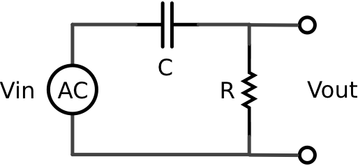
Build the following circuit on a breadboard using a 1000 kOhm resistor and a 0.1 microFarad capacitor. Note that the power supply is an AC voltage source.
Connect channel one of an oscilloscope to measure the input voltage and channel two to measure the output voltage across the resistor. Vary the frequency of the AC voltage source and monitor the input and output waveforms on the oscilloscope.
What happens to the amplitude of the output as the frequency of the input increases/decreases?
What you have built is a passive analog high-pass filter. Such a device only allows sufficiently high frequency components of the input waveform to pass to the ouput.
Gather data to construct a plot showing Vout/Vin as a fuction of frequency. This frequency response curve is called a Bode plot.
Estimate the frequency at which the amplitude of the output is exactly half the amplitude of the input.
The theory of RC (Resistor/Capacitor) filters is well defined but requires knowledge of complex numbers and is thus largely beyond the scope of this course. However, it can be shown that passive analog high-pass filters like the one built here have a cut-off frequency in Hz equal to
fcut-off = 1/(2πRC)This means that an ideal high-pass filter would allow any frequency above this cut off to pass unattenuated while eliminating signal frequencies below this cut off. In the real word, as your Bode plot shows, the cut off frquency is not a sudden all-or-nothing threshold but the middle of a gradual sloping transition from frequencies that are completely attenuated to freqencies that are completely transmitted.
How does the theoretical cut-off frequency for your circuit compare to the experimental value obtained from your Bode plot?
Another property of analog filters is the propensity to cause a phase shift in the output relative to the input. In other words, the peaks and valleys of the input and output do not line up.
Make a plot of the phase shift (in radians) of the output relative to the input as a function of frequency.
Does the high-pass filter cause the output to be delayed (peaks in output happen after peaks in input) or advanced (peaks in output happen before peaks in input) in time?
Low-Pass Filter
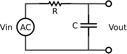
Build the following circuit by changing the position of the resistor and capacitor in the circuit you built above.
This is a low-pass filter.
Construct a Bode plot for this circuit’s output relative to its input.
Estimate the frequency at which the amplitude of the output is exactly half the amplitude of the input.
The theoretical cut-off frequency for this low-pass filter is also
fcut-off = 1/(2πRC)An ideal low-pass filter would allow any frequency below this cut off to pass unattenuated while eliminating signal frequencies above this cut off.
How does the theoretical cut-off frequency for your circuit compare to the experimental value obtained from your Bode plot?
Make a phase shift plot for the low-pass filter’s output relative to its input as a function of frequency.
Does the low-pass filter cause the output to be delayed (peaks in output happen after peaks in input) or advanced (peaks in output happen before peaks in input) in time?
Assignment
Turn in a Bode plot and phase shift plot for each of your circuits indicating on the Bode plots the theoretical cut-off frequency for your circuits.
Experiment with differnt capacitor and resistor values that yield the same cut-off frequency. How does the slope of the Bode plot in the cut-off region depend on the values of the capacitor and resitor used?

