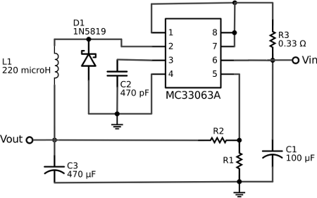
The voltage regulator built onto the Arduino Uno is a linear-type regulator and is horribly inefficient. If you are running the ATmega238 at 5V using a 9 V battery, approximately half of the battery’s energy will be dissipated as heat by the regulator. This post demonstrates a DC/DC switching-type voltage regulator circuit that can be use with a breadboard Arduino and is much more efficient then a typical 7805 regulator. The switching regulator used is a Texas Instruments MC33063A. This IC can be used with external components to make a boost regulator (to step up voltage), a buck regulator (to step down voltage), or an inverting regulator. Here I am setting it up as a buck regulator to step down a 12 V battery pack to run a 3.3 V breadboard Arduino and XBee radio. Here is the voltage regulator circuit schematic.
The values of R1 and R2 determine the output voltage according to the following formula:
Vout = 1.25(1+R2/R1)In my design, I am using R1 = 100 kOhm and R2 = 200 kOhm giving me an output voltage of approximately 3.75 V to power both an ATMega328 and an XBee Series 1 radio.
Depending on the values of R1 and R2, this switching regulator circuit uses about 2.5 to 3.5 mA of current when not powering a load. This compares to about 10 – 15 mA for a 7895 linear regulator. By using this regulator circuit design, my battery lasts for almost two weeks.

Permalink //
I think L1 was probably meant to be a 220uH inductor?
Permalink //
Thanks, you are absolutely correct. I will update the schematic.
Permalink //
Any chance you have a picture of your breadboard?
Thanks
Permalink //
I don’t have one but the next time I build this circuit I will take a picture and post it.
Permalink //
hello,
i want low voltage regulator using ic MC33063A.
can i buy it ready made?
thanks
Permalink //
Can I give 5v at Vin ?
Permalink //
Hi
You can use LM2576ADJ.
http://www.onsemi.com/pub/Collateral/LM2576-D.PDF